If you're just trying to do ordinary GPIO on your beaglebone, this is not the page you're looking for.
This is about how to use certain GPIO pins on the beaglebone using the two embedded 200MHz PRU microcontrollers using their super-fast Enhanced GPIO mode. The PRUs can also be used to access other GPIO pins, but not as quickly, and I don't cover that here.
Reading all the way through chapters 6 and 13 of Exploring BeagleBone was the best resource I found for understanding all this, but at the end of the day, here's what I had to do:
- sudo apt-get update && sudo apt-get dist-upgrade
- Create a device tree overlay, compile it, reboot, and enable it
- Assemble my PRU code (just 3 instructions!)
- Compile a tiny C program to send the code to the PRU.
One challenge is that most of the info out there is from 2013 or 2014, when you had to install PRUSS manually. Fortunately, that stuff all came by default on my BeagleBone Green and BeagleBone Black. So you don't have to worry about installing am335x_pru_package to get pasm and libprussdrv!
Turns out programming the PRU is the easy part. The hard part is sorting out all the different ways of doing GPIO and getting the right mode enabled in the device tree.
Choosing the Right Pins (it's harder than you think)
This table shows which GPIO pins you can access from the PRUs using Enhanced GPIO (EGP). The "BB Header" column shows you the physical header pin on the BeagleBone. The R30 and R31 columns show you which pins you'll be writing or reading when you access that bit on those registers from the PRU0 or PRU1 microcontrollers.
But it's not the whole story -- if you have a BeagleBone Black, all of the pins for PRU1 are used by the HDMI or onboard flash (emmc2). So to use those pins, you have to disable HDMI or onboard flash (and thereafter boot from a microSD card) first, which requires editing the uEnv.txt file and rebooting. (BeagleBone Green doesn't come with HDMI, freeing up those pins by default.)
These tables for headers P8 and P9 from Exploring BeagleBone highlight those reserved pins in red, and then show in the rightmost column that they're reserved for HDMI or emmc2.
Note from the first table that even though each PRU supports 16 EGP pins, the BeagleBone headers don't expose them all. So don't expect to do fast 16-bit parallel I/O from a PRU on your BeagleBone.
Finally, it looks like pins 41 and 42 on P9 are yet another special case, and are overloaded with other GPIO pins somehow, and so you have to set those pins as inputs before using them from the PRU. (I didn't try).
Let's avoid all those special cases and pick two pins that aren't already spoken for. We'll use pin 11 on header P8 for output. The tables show us that P8_11 correspond to PRU 0, register 30, bit 15. In the PRUs, R30 is a "magic" register, and writing to it lets us set the state of output pins.
Let's also pick a pin for input, pin 16 on P8. There the tables show us that P8_16 corresponds to PRU 0, register 31 bit 14. R31 is the other "magic" PRU register, and reading from it reads input pins.
Get the Pin Configuration Right!
This is really easy to screw up. The first thing we need to find is the multiplexer mode, which determines whether the pin will be hooked up to the PRU, HDMI port, etc.
The modes are nicely laid out as 7 columns in the P8 and P9 tables from the book. At first you might think that Mode6 is "PRU input" mode, since there are lots of green cells like "pru_pruX_r31_XX", and r31 is the magic PRU input register. But P8_11 and P8_12 break this rule. So it's better to assume the pinmux modes were assigned at random, and check carefully in the tables. I'm glad I printed them out, since I've had to stare at them a lot.
We want P8_11 to be our output pin, because the P8 table doesn't list it as colliding with anything important, and because it's highlighted in green, showing that it can work with PRU EGP. Its name in that cell is pr1_pru0_pru_r30_15. "pru0" tells us it's for PRU0. "r30" tells us it can be used as an output, since r30 is the magic output register. And it's in the "mode6" column, so we know we need to set that pin to mode 6 if we want to use it from the PRU0's register 30.
We can also get that from the elinux.org table, since the "Pinmux Mode" to the right of the R30(output) column is Mode_6.
For our input pin P8_16, when we follow the tables we see that it's also mode 6 in this case.
But as explained in the Exploring BeagleBone book (and less clearly in table 9-60 of the TRM), we're not done yet! There are 4 other settings that can apply to each pin:
Bits 0..2 are the multiplexer mode (these two pins are both 6)
Bit 3 enables (0) or disables (1) the internal pullup/pulldown resistor
Bit 4 is 0 for pulldown, 1 for pullup
Bit 5 is 0 to disable input, 1 to enable input.
Bit 6 is 1 if you want slow rise/fall times (for long i2c buses)
So for our output pin, P8_11, our configuration value is just 0x6, since none of the other bits are set.
But for our input pin P8_16, we need to turn on bit 5, so the value is 0x26 (10000 binary ORed with 110 binary).
Device Tree Overlays (there is NO escape!)
I looked all over, and there doesn't seem to be a way around creating and editing device tree overlays.
Now that we've picked what pins we want to use with the PRU, we have to use the device tree to enable the PRUs and put those pins into the right mode.
 // This DTS overlay sets up one input and one output pin for use by
 // PRU0 via its Enhanced GPIO mode, which will let us access those pins
 // by writing to R30 bit 15 or reading from R31 bit 14.

 // Save this file wherever you want (but I recommend /lib/firmware), as
 // "PRU-GPIO-EXAMPLE-00A0.dts".

 // Compile with:
 // dtc -O dtb -I dts -o /lib/firmware/PRU-GPIO-EXAMPLE-00A0.dtbo -b 0 -@ PRU-GPIO-EXAMPLE-00A0.dts

 // You'll have to reboot, after which you can do this as root to activate it:
 // echo PRU-GPIO-EXAMPLE > /sys/devices/bone_capemgr.?/slots

 /dts-v1/;
 /plugin/;

 / {
   // This determines which boards can use this DTS overlay
   compatible = "ti,beaglebone", "ti,beaglebone-green", "ti,beaglebone-black";

   // I think part-number is supposed to correspond with the filename,
   // so we'd save this as "PRU-GPIO-EXAMPLE-00A0.dts".
   part-number = "PRU-GPIO-EXAMPLE";

   // This always seems to be 00A0, and all the .dtbo files in /lib/firmware
   // seem to be named foo-00A0.dtbo, but then are loaded without that suffix.  So
   // for foo-00A0.dtbo we'd do 'echo foo > /sys/devices/bone_capemgr.?/slots'
   version = "00A0";

   // List the pins and resources we'll be using. This table:
   // http://elinux.org/Ti_AM33XX_PRUSSv2#Beaglebone_PRU_connections_and_modes
   // shows which pins can be used with PRU0 and PRU1 for input and output via
   // registers R31 and R30.
   // Our output pin, P8_11, corresponds to PRU 0, register 30, bit 15
   // Our input pin, P8_16, corresponds to PRU 0, register 31, bit 14
   //
   // Beware: Many other PRU EGP pins are reserved by HDMI or onboard flash, which
   // would need to be disabled first by editing uEnv.txt and rebooting.
   exclusive-use =
      "P8.11", "P8.16", "pru0";

   fragment@0 {
    target = <&am33xx_pinmux>;
    __overlay__ {
      example_pins: pinmux_pru_pru_pins {

       // The offset and mode for pins P8_11 and P8_16 also come from the table linked above.
       //
       // That table gives offset 0x34 for P8_11, and 0x38 for P8_16.
       // It also shows us we want pinmux mode 6 for P8_11 in output mode,
       // and again pinmux mode 6 for P8_16 in input mode.
       //
       // Table 9-60 in the TRM: http://www.ti.com/lit/ug/spruh73l/spruh73l.pdf
       // helps us calculate the rest of the configuration value.
       //
       // For P8_11, the other fields are all 0, so the value is just 0x06.
       //
       // For P8_16, we want it to be an input, so we also set bit 5, yielding
       // a value of 0x26. We could also set bits 3 and 4 to enable a pullup
       // or pulldown.
       pinctrl-single,pins = <
         0x34 0x06
         0x38 0x26
       >;
      };
    };
   };

   // This enables the PRU and assigns the GPIO pins to it for use in EGP mode.
   fragment@1 {
    target = <&pruss>;
    __overlay__ {
      status = "okay";
      pinctrl-names = "default";
      pinctrl-0 = <&example_pins>;
    };
   };
 };
After saving that to /lib/firmware/PRU-GPIO-EXAMPLE-00A0.dts, I compiled it:
root@beaglebone:/lib/firmware# dtc -O dtb -I dts -o /lib/firmware/PRU-GPIO-EXAMPLE-00A0.dtbo -b 0 -@ PRU-GPIO-EXAMPLE-00A0.dts
And then I had to reboot before the system would let me load it. The "PRU-GPIO-EXAMPLE" and the "L" in "P-O-L" shows me that the overlay loaded successfully.
 root@beaglebone:/lib/firmware# echo PRU-GPIO-EXAMPLE > /sys/devices/bone_capemgr.?/slots
 root@beaglebone:/lib/firmware# cat /sys/devices/bone_capemgr.?/slots
  0: 54:PF---
  1: 55:PF---
  2: 56:PF---
  3: 57:PF---
  4: ff:P-O-L Bone-LT-eMMC-2G,00A0,Texas Instrument,BB-BONE-EMMC-2G
  5: ff:P-O-L Override Board Name,00A0,Override Manuf,BB-UART2
  6: ff:P-O-L Override Board Name,00A0,Override Manuf,PRU-GPIO-EXAMPLE
Writing Code (finally!)
Now that the hard part's done, we can write some assembly code for the PRU and some C code to load it. Here's the C code that runs on the main CPU and lets us load an arbitrary PRU .bin file into PRU 0:
 // Loads an arbitrary .bin file into PRU0 and waits for it to signal
 // that it has finished.
 //
 // Pass in the filename of the .bin file on the command line, eg:
 // $ ./pru_loader foo.bin
 //
 // Compile with:
 // gcc -o pru_loader pru_loader.c -lprussdrv

 #include <stdio.h>
 #include <prussdrv.h>
 #include <pruss_intc_mapping.h>

 int main(int argc, char **argv) {
  if (argc != 2) {
   printf("Usage: %s pru_code.bin\n", argv[0]);
   return 1;
  }

  // If this segfaults, make sure you're executing as root.
  prussdrv_init();
  if (prussdrv_open(PRU_EVTOUT_0) == -1) {
   printf("prussdrv_open() failed\n");
   return 1;
  }

  tpruss_intc_initdata pruss_intc_initdata = PRUSS_INTC_INITDATA;
  prussdrv_pruintc_init(&pruss_intc_initdata);

  // Change to 1 to use PRU1
  int which_pru = 0;
  printf("Executing program and waiting for termination\n");
  prussdrv_exec_program(which_pru, argv[1]);

  // Wait for the PRU to let us know it's done
  prussdrv_pru_wait_event(PRU_EVTOUT_0);
  printf("All done\n");

  prussdrv_pru_disable(which_pru);
  prussdrv_exit();

  return 0;
 }
And here, finally, is the assembly code that runs on the PRU. "set r30, r30, 15" is all it takes to turn on our pin, and "clr r30, r30, 15" is all it takes to shut it off!
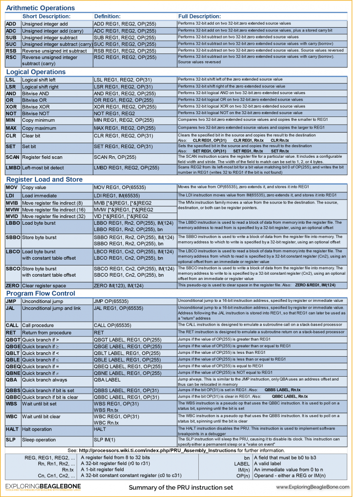
Here's a lovely PRU instruction set quick reference, also from the book. Print it out too.
 // Demonstrates using Enhanced GPIO (EGP), the fast way to
 // do GPIO on certain pins with a PRU.
 //
 // Writing to r30 with PRU0 or PRU1 sets the pins given in this table:
 // http://elinux.org/Ti_AM33XX_PRUSSv2#Beaglebone_PRU_connections_and_modes
 //
 // But only if the Pinmux Mode has been set correctly with a device
 // tree overlay!
 //
 // Assemble with:
 // pasm -b pru_egp_output.p

 // Boilerplate
 .origin 0
 .entrypoint TOP

 TOP:
  // Writing bit 15 in the magic PRU GPIO output register
  // PRU0, register 30, bit 15 turns on pin 11 on BeagleBone
  // header P8.
  set r30, r30, 15

  // Uncomment to turn the pin off instead.
  //clr r30, r30, 15

  // Interrupt the host so it knows we're done
  mov r31.b0, 19 + 16

 // Don't forget to halt or the PRU will keep executing and probably
 // require rebooting the system before it'll work again!
 halt
I assembled with "pasm -b pru_egp_output.p", loaded it with "sudo ./pru_loader pru_egp_output.bin", and verified with my voltmeter that P8_11 showed 3.3v. Then I uncommented the clr, reassembled, re-ran and verified that it dropped to 0. Success!
Now we're ready for the big leagues, 5 whole instructions to copy the value of the input pin to the output pin:
 // Demonstrates using Enhanced GPIO (EGP), the fast way to
 // do GPIO on certain pins with a PRU.
 //
 // Writing to r30 or reading from r31 with PRU0 or PRU1 sets or reads the pins
 // given in this table:
 // http://elinux.org/Ti_AM33XX_PRUSSv2#Beaglebone_PRU_connections_and_modes
 //
 // But only if the Pinmux Mode has been set correctly with a device
 // tree overlay!
 //
 // Assemble with:
 // pasm -b pru_egp_io.p

 // Boilerplate
 .origin 0
 .entrypoint TOP

 TOP:
  // Reading bit 14 in the magic PRU GPIO input register 31
  // bit 14 for PRU0 reads pin 16 on BeagleBone header P8.
  // If the input bit is high, set the output bit high, and vice versa.
  QBBS HIGH, r31, 14
  QBBC LOW, r31, 14

 HIGH:
  // Writing bit 15 in the magic PRU GPIO output register
  // register 30, bit 15 for PRU0 turns on pin 11 on BeagleBone
  // header P8.
  set r30, r30, 15
  QBA DONE

 LOW:
  clr r30, r30, 15

 DONE:
  // Interrupt the host so it knows we're done
  mov r31.b0, 19 + 16

 // Don't forget to halt or the PRU will keep executing and probably
 // require rebooting the system before it'll work again!
 halt
I tested it by installing a jumper from P9_01 (GND) or P9_03 (DC_3.3V) to P8_16. Be sure not to connect to P9_05 or P9_06 though, since those are at 5V and could blow up your board!
Where to now?
If you're still with me, you probably have something fancier in mind than just turning a pin on or off. Even though am335x_pru_package came installed on my BBB, the examples weren't there. You can find them here on github: https://github.com/beagleboard/am335x_pru_package/tree/master/pru_sw/example_apps
In particular, PRU_memAccessPRUDataRam was super helpful. It doesn't use any GPIO pins, so it only requires that the PRUs are enabled (which you get if you use my overlay above). I was trying to get some assembly code to work, and couldn't get any signal back from the PRU to know if it wasn't working or if it just couldn't toggle any GPIO pins. I had deleted that pesky "interrupt the host" instruction at the end of my listing above, so I was running the code totally blind. When I discovered that PRU_memAccessPRUDataRam worked fine on a clean boot, but would no longer work after running my code, I quickly realized that I had forgotten to put a HALT instruction at the end of my code.
One other thing to explore is the new C compiler for the PRUs, PRUSS-C. It's also installed by default on my beaglebones. It looks pretty neat, but I haven't managed to get the code onto a PRU yet. Something to do with .cmd scripts for hexpru, I think.
Finally, TI also has a GUI development suite for their processors. I was tempted to try it, but they make you create a login to myTI first, and I'd rather use command line tools anyway.
37 comments:
Hi
I have a BBB, with Linux version 3.8.13.
I'm trying to convert an existing .p file (from Molloy's example 13.A1, which works)
I want it to run a loop on the PRU so that it loads 4096 samples into a memory block which can be read from Linux space. Problem is I haven't done any assembler for 40 years, so I'm a bit rusty.
Any suggestions gratefully received.
C is no problem, so I've tried installing Pruss_C - the 32 bit version for ARM but it complains that:
clpru commnand is not found.
I haven't had success with the c compiler yet, something about linker scripts. The assembly instruction set for the PRU is pretty clean although the "branch less than" and its ilk have their operands backwards from what I expected. Happy to look at your assembly and hear about how you're debugging.
Hi Peter,
Great work. With lots of digging I've manage to get to the same place you have. I'm trying to go one step farther, instead of using just the enhanced gpio's I'm looking to use the general purpose gpio's from the PRU also. The reason being is, I'd like to be able to continue using my LCD along with toggling PRU I/O.
I just haven't found the magic yet, have you had any experience with this yet?
Regards,
Mark
Mark, in the "Exploring Beaglebone" book there's a "Utilizing Regular Linux GPIOs" in chapter 13 that includes this example: https://github.com/derekmolloy/exploringBB/blob/master/chp13/gpioLEDButton/ledButton.p
Awesome job. I didn't want to shut down my hdmi (running headless) to just toggle a pin or two. I have been many places on the internet researching this, but I think you were the only one so far that have figured this out. Kudos and many thanks
Very nice article, just what I'm after.
One more thing: I want to be able to take several readings from the GPIO pins, and append the data from one of the registers to a file, such that the file is accessable by linux. I'd need to make several hundred such appendments.
Do you know what command should be used to save the register somewhere?
lachlan_boyle, this article might get you closer to what you want:
http://credentiality2.blogspot.com/2015/09/beaglebone-pru-ddr-memory-access.html
It shows how the PRU and CPU can access shared memory.
Thanks for posting this!!
It's been really helpful in getting started with the PRU's
For whatever reason, I couldn't replicate the results of any of the other PRU resources I've gone through, but this one worked easy peasy. Thanks for taking the time to make such a nice write up!
Very nice. I think "sudo ./pru_egp_loader pru_egp_output.bin" should use ./pru_loader perhaps.
Right you are, Ken! Fixed.
Hi !
I try to use your code with writing and reading (the last) but the code never stopped and didn't really worked. I just changed two lines because I read on P8_20 pin so I have QBBS HIGH, r31, 13 and QBBS LOW, r31, 13.
I use another beaglebone (BBB2) to send a signal (which is a HIGH/LOW signal) on P8_11 to P8_20 of the other beaglebone (BBB1). I have an LED on P8_11 (on BB1)to see the state of the output
When I run the code on BBB1, the LED never light on and I didn't see "All done" in the terminal.
Have you any idea?
Thanks for your help :)
Bob, start by trying the example code exactly as written and see if that works. Also, you said "QBBS HIGH, r31, 13 and QBBS LOW, r31, 13", which means:
if bit 13 of r31 is set, jump to HIGH
if bit 13 of r31 is set, jump to LOW
In the example code, it's QBBS and then QBBC.
I'm sorry, I made a mistake. I wrote QBBC LOW, r31, 13 in my code. I changed the bit 14 to 13 reffered to the table you give (this link: http://elinux.org/Ti_AM33XX_PRUSSv2#Beaglebone_PRU_connections_and_modes) because P8_20 is an input and the table said that the bit is 13 for register 31.
I have just tried the example by copy/paste your code but it didn't work with me.
Did you get HDMI disabled in uEnv.txt, and did you get the device tree overlays loading correctly? Is the PRU enabled when you do this? cat /sys/devices/bone_capemgr.?/slots
Yes HDMI is disabled when I enter the cat /sys/devices/bone_capemgr.?/slots command but I have nothing in uEnv.txt . There is no "L3 (just P - O - -)
I have a code inspired from your first code which blinks a LED and works without any issue. I use your .dts code.
Edit from my last comment: There is no "L"
Then either you didn't "echo PRU-GPIO-EXAMPLE > /sys/devices/bone_capemgr.?/slots" as root, or you need to check dmesg to see why it didn't load.
I was as root evrytime. But my problem is solved. In fact, I did echo[...]slots before going to the folder where I have my code and it works. I find this a bit strange...
Thanks again for your help !
Hey there! Thanks for the article, this has helped me a lot!
I have a question though, may or may not be a "dumb" question. If I read the table correctly I have to write bit 0 to R30 to turn on P8.45, but writing bit 0 to R30 also turns on P9_31. The only difference is that P8_45 is on PRU1 and P9_31 is on PRU0.
Do you know if writing bit 0 to R30 turns on both pins or is there a way to specify a single pin to turn on?
Tony, PRU0 and PRU1 are the two realtime microcontrollers, and they each have their own R30 and R31 registers. So if you wanted to toggle P8.45 you'd load your code into PRU1 and set R30 bit 0, but if you loaded that same code into PRU0 instead, you'd be toggling P9.31.
Thanks for your answer to my previous comment. =) One more question: when trying to run your code I get a prussdrv_open() failed message. Checking dmesg shows me: pruss_uio 4a30000000.pruss: No children.
I've tried googling around to see if I could solve it but nothing has helped. Any ideas?
I haven't seen that error before. Looks like an issue with the .dtbo files or the uio_pruss kernel module.
HI
I WANT TO KNOW HOW THE DATA CAN BE SENT TO GPIO THROUGH PRU PARALLELY.
HOW TO STORE THE DATA IN R30 REGISTER AND ACCESS THAT THROUGH GPIO PINS PARALLELY
Chaitanya, you'll have more success getting help online if you use appropriate capitalization. Using ALL CAPS makes it sound like you're shouting. If you want to write multiple bits of r30 at once, you could do something like "mov r30, 0x12345678".
Haha, I will not use caps from now. If we move the value into r30 will it automatically send the data to GPIO pins?
Correct, assuming you set up the device overlay correctly.
Hi,
very good explained tutorial but I'm stuck at the point where I have to load the overlay:
/sys/devices/bone_capemgr.?/slots: No such file or directory
I'm running latest debian image (bone-debian-8.6-lxqt-4gb-armhf-2016-11-06-4gb.img / Linux beaglebone 4.4.30-ti-r64 #1 SMP Fri Nov 4 21:23:33 UTC 2016 armv7l GNU/Linux) from sd card and followed all steps.
Could you give me a hint what I am missing?
Poke around the filesystem some more, perhaps use find to look for files named 'slots' (eg., 'find / 2>/dev/null | grep slots'). Those files relate to the device tree in general, not just the PRU. So if they're gone you've got bigger problems than just not being able to use the PRU. Hopefully they just got renamed or something. (Are you on an old beaglebone white perhaps? I seem to recall those having different hardware)
great, it looks like it is moved to:
/sys/devices/platform/bone_capemgr/slots
# cat /sys/devices/platform/bone_capemgr/slots
0: PF---- -1
1: PF---- -1
2: PF---- -1
3: P---L- 0 4D 4.3 LCD CAPE- 4DCAPE-43T ,00A1,4D SYSTEMS ,BB-BONE-LCD4-01
4: P-O-L- 1 Override Board Name,00A0,Override Manuf,PRU-GPIO-EXAMPLE
Thanks for the update
After loading the overlay I had the problem that prussdrv_open function failed.
Solution is found here (instead of am335x-boneblack.dts you have to use the certain file which is loaded in your /boot/uEnv.txt - for me am335x-boneblack-emmc-overlay.dtb):
https://groups.google.com/forum/#!topic/beagleboard/1rIV-mR8wYw
Now I can run the sample pru code but I can't see the Pin8_11 going to high.
./pru_loader pru_egp_output.bin
Executing program and waiting for termination
All done
I think the problem is related to this:
root@beaglebone:/sys/kernel/debug/pinctrl/44e10800.pinmux# cat pins |grep 'pin 13\|14'
...
pin 13 (44e10834.0) 00000027 pinctrl-single
pin 14 (44e10838.0) 00000027 pinctrl-single
...
the value stays the same before and after loading the overlay (I just copied your example).
I expect it to change to 00000006 // 00000026 after loading it.
dmesg output while loading the overlay:
[ 55.982283] bone_capemgr bone_capemgr: part_number 'PRU-GPIO-EXAMPLE', version 'N/A'
[ 55.982365] bone_capemgr bone_capemgr: slot #4: override
[ 55.982408] bone_capemgr bone_capemgr: Using override eeprom data at slot 4
[ 55.982456] bone_capemgr bone_capemgr: slot #4: 'Override Board Name,00A0,Override Manuf,PRU-GPIO-EXAMPLE'
[ 56.001688] bone_capemgr bone_capemgr: slot #4: dtbo 'PRU-GPIO-EXAMPLE-00A0.dtbo' loaded; overlay id #1
any ideas what could still go wrong here?
Agreed, if the pin mode is wrong, GPIO probably won't work. Perhaps it's possible to change the pin mode manually using one of the /sys/ files? That would increase our confidence that the problem is related to the device tree overlay. I know Kumar over at BeagleLogic had a lot of trouble with device tree compiler versions getting out of sync with the kernel. The compiled .dtbo files then would tend to fail silently. So your update to recent debian may be part of the issue you're seeing.
Finally I got it working!
I started with another image (Debian 8.6 2016-12-09 4GB SD IoT) and did all steps again - but ended with the same behaviour.
Then I tried an alternative overlay:
generated by this site: http://kilobaser.com/blog/2014-07-28-beaglebone-black-devicetreeoverlay-generator
Now the pinmux for pin 13 is changed as expected and I can toggle the output by pru.
I think there is a problem with your example overlay (at least with latest debian image) but I didn't investigate for differences yet.
Now I can move on to the productive part ;)
Works like a charm for Debian distro with Kernel 3.8. However, for some reason the dtc does not work for Kernel versions 4.1 and greater. I think this is an issue still being looked into by many folks.
Do I really need to create the firmware? Could I just export the appropriate gpio pin with the same effect?
Depends what effect you're trying for
Post a Comment