Monday, February 17, 2020

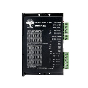
Longs Motor DM542A idle current bug

Stepper motor drivers like this one usually have a jumper (that's usually SW4) that sets idle current.  So if you haven't sent any pulses in a while, rather than cooking your stepper by holding full current, it'll cut it down to half current:
Image result for dm542a
But I just noticed a bug on my Longs Motor DM542A: when it first powers on, it comes on at full current (the whole unit drawing about 1.3A at 32V) and stays there.  But if I move that axis (send the driver some pulses), then after I'm done it drops down to about 630mA.

So to work around this issue, make sure you move your steppers a little after powerup so that the half-current mode kicks in.

Also, I discovered that the half-current mode seems to actually be "half power" mode -- the current only goes down to about 70% of full, rather than 50%.

BTW, I checked this behavior against a stpperonline DM556S, and it does the opposite: it draws very little power until it gets its first step pulses, then moves up to half current.

Thursday, February 15, 2018

Teardown: Miller RFCS RJ45 tig welding foot pedal

[Gallery with hi-res versions of the photos shown here]

Tig welding pedals are expensive, mostly over $100.  Miller wants $150 for the RFCS-RJ45 pedal that goes with the Multimatic 215, and $600 for their wireless pedal.  So I'm not the first person to wonder whether something cheaper like a musician's expression pedal might work just as well.

The RFCS-RJ45 is unusual in using an RJ45 connector instead of the more common 14-pin connector.  RJ45 is less rugged but very common, and one nice feature of the RFCS-RJ45 is an RJ45 socket inside the pedal, so that the cable can be replaced with a standard ethernet cable using just a screwdriver.

The pinout for the RJ45 is given on page 15 of this Diversion 165/180 manual, and is the same for the Multimatic 215.  Note that in that manual, pins 6 and 5 are listed out of order.  In order, the nominal pinout is:


  1. +10VDC supply for foot pedal position
  2. 0-10V foot pedal position
  3. common for foot pedal
  4. +15VDC supply for contactor control switch
  5. foot control select, to be tied to pin 7.  (Seems to do nothing on multimatic 215)
  6. contactor control, enable by tying to pin 4
  7. chassis common
  8. no connection
So the simplest pedal we might imagine would be, say, a 1K potentiometer on pins 1-3 for current control, and a switch connecting pins 6 and 4 to start welding.


Miller did something more interesting than that, though, as we can see when we look inside.  No moving parts!

Theory of operation:

Potentiometers can be finicky and unreliable over time, as everyone knows who's ever owned  a stereo with a scratchy volume knob.  And in fact audiophiles often pay over $100 for really high quality pots.  

So miller opted instead to use a hall effect sensor instead.  The screw you can see on the underside of the lid holds a little magnet, and U3, the little 3-pin IC between the springs, is labeled 324, so it's probably this hall effect sensor.

Also of note is the pic 16f689 microcontroller the pair of chips marked VBHI, which are probably these op amps, and U5 marked D2B, which is probably this 8-bit DAC.

So I'm betting one op amp cleans up the signal from the hall effect sensor, feeds it to the pic which applies factory calibration data, and then uses the DAC to generate the simulated potentiometer output, which is then scaled up to the 0-10V range by the second op amp.

Signals:

I sacrificed an ethernet cable and used a breadboard to break out the 8 lines.  I measured voltage and current on each pin of the RJ45. 

12-15mA flows from pin 1 to pin 3, so the board seems to be using the 10V supply to power itself.

Pin 2 has the 0-10V signal reporting foot position.  Mine doesn't pull quite all the way to 10V, but it gets pretty close.

I was a bit surprised to only read 40-100uA of current flowing through pin 2.  Since welding is so electrically noisy, I figured they might draw several milliamps from the sense line to drown out any picked up noise.  But I also imagine there are plenty of pedals floating around the market that use high resistance pots which would sag under that load, so 100uA seems to be the compromise they chose.

Pin 4 does indeed have around 15V on it, with no observable current flowing through it.

Pin 5 doesn't seem to do anything on the multimatic 215.

According to the manual, pin 6 should get tied to the 15V on pin 4 to enable the contactor, but my RFCS-RJ45 only pulls up to about 9.8V when I press the pedal.  Not too surprising; they were already working with 10V and didn't want to get the 15V rail involved unnecessarily.  I measured 650uA flowing through this pin when the switch was pressed.


Nothing of interest on pins 7 or 8.

Substituting a musician's expression pedal

So can we swap in a musician's cheap Moog EP3 expression pedal and save some cash?  Two potential issues:

1. You need to control the contactor somehow.  One option would be to use a switch separate from the foot pedal, and musician gear has plenty of those.  In such a setup, your foot has to find the switch, get back to the pedal for current control, then find the switch again to shut off the arc.  (And don't bump the switch on by accident, because now you've got a torch that's hot until you hit the switch again).  But if you want the traditional single action, you'd need to, say, rig up a switch to the expression pedal for contactor control.

2. A brief search suggests that expression pedals use 10-25k ohm pots.  A 10k pot across 10V flows 1000uA, so the 40-100uA drawn by the welder is enough to cause some sag, but you'd probably get away with it.  25k might be pushing it.  Also, I see some reports that the EP3 pedal in particular has a logarithmic response, whereas you probably want linear for welding.


Wednesday, September 27, 2017

Home made cold slab ice cream

Executive summary: With an 11 pound slab of aluminum chilled in my freezer overnight, I can make one small 30g serving of ice cream.  Other promising avenues include brine instead of aluminum, and dry ice + alcohol (which gets waaaay colder than your freezer).

----

I was daydreaming about 3D ice printers, and it occurred to me that I might be able to make Cold Stone style ice cream if I put a big chunk of metal in the freezer.

My first thought was to use steel, but aluminum turns out to have almost twice the specific heat of steel and about 4 times the thermal conductivity.  So for a given weight it can absorb more heat, and do it faster.

I had an 11 pound hunk of 4"x4"x12" aluminum left over from the rotary mill, so I cleaned it up and put it in the freezer for a few hours.


The tape was to help me more accurately measure the temperature with an infrared temperature gun, but I think a contact thermometer would be better.


I used a 1:1:1 mixture of cream, sweetened condensed milk and fresh strawberries.  I'm not sure how much the cream adds to the experience, so I think it'd be worth trying just sweetened condensed milk + strawberries.


But even after lots of waiting and pushing it around on the plate, it never quite froze (but read on!).


Doing the math: should we expect it to work?

Later it occurred to me to work out the heat of fusion of the ice cream and see how that compares to the heat required to take the plate from my freezer's ~0F to 32F.  Wolfram Alpha tells me that "specific heat of aluminum * 11 pounds * 15 K difference" takes 67,700J, whereas 100g of water (~5.5 moles) needs to lose about 30kJ to freeze.  So that says my big chunk of aluminum should be able to absorb 2x as much energy as I need to freeze a small serving of ice cream, but that's assuming it starts at 0F and doesn't count any other losses (like ingredients that need to be cooled down to 32F, and absorbing ambient heat from my kitchen).

So I'll give it another go with the plate freezing overnight, but I suspect I'd need to start out colder than 0F to really make it work.  

And that makes me think this guy's clever solution of dry ice (-109F) cooling a griddle through an interface of liquid alcohol is probably a better solution.

Take 2:

On second thought, I think my IR thermometer may have been telling me something useful.  On my first attempt, it claimed the plate was only down to about 20F.  Leaving it in the freezer overnight and turning down the thermostat a bit, the plate got down to under 10F, and I made my first successful batch:


One spoonful of cream, one spoonful of sweetened condensed milk, and one spoonful of strawberries came out to about 30g.


Still marginal:

I tried a second serving right after the first, but it wouldn't freeze.  So 30g seems to be about the limit for this plate at this temperature.  I'm not sure how much of that is due to the ingredients warming up, the plate warming up as a whole, or the first batch putting too much heat into the surface of the plate (and it not being able to dissipate quickly enough into the core).

I pulled out the Flir One to see if I could sense one face of the plate being warmer than the others.  Aluminum tends to reflect thermal IR, and in the video below you can see it acting like a mirror:


Mostly it's reflecting heat from the rest of the room and the cold towel it's sitting on.  You can see some fingerprints after I touched it, and I'm not sure if that's something to do with condensation or with giving it more heat to emit, such that it's noticeable over the reflection.

To combat emissivity issues, I put a strip of tape around the four sides, since the tape won't reflect LWIR like the aluminum does.  Unfortunately, I only did this test after rinsing off the plate in the sink, which seems to have warmed it up (or at least the outer region of the plate) quite a lot and overwhelmed any evidence left from the ice cream session.


But based on earlier photos like this one, I'd guess that the heat gain is more uniform than localized.  (And I think this photo shows less reflection than the video because there was icy condensation on the plate at that time).  Maybe somebody with a better background in thermals could comment with a back-of-envelope calculation on how fast we'd expect the heat to dissipate into the core of the plate.


Saltwater instead of aluminum?

Also note Damien's suggestion below about using brine as a cold source.  Looks like a salt water solution above 33% freezes to -6F, so it gets cold enough for us.  And looks like its heat capacity is about 3300 J/(kg * K) compared to Aluminum's 910 J/(kg * K).  So it holds over 3x as much cold by weight (and since it's lighter, it has a smaller advantage by volume as Damien cites).

Weirdly though, for thermal conductivity, aluminum is reported as 205 W/(m*K) and brine says it's around 0.4 -- that's a 500x difference!  I expected completely the opposite, since liquids have natural convection and good thermal interfaces to neighboring materials.  So maybe the way they test thermal conductivity somehow controls for those factors, because I'd certainly expect putting my hand in freezing brine to be at least as chilling as putting it on a slab of aluminum.

Of course salt water is also way cheaper than aluminum.  So a thin hollow vessel, say, a box made out of thin stainless steel plate, ought to be cheaper and more effective by weight, assuming my intuition is right about brine's conductivity.  The most annoying part might be keeping the box sealed and avoiding bubbles, since we want to freeze our cream on the top surface of the box, and air bubbles won't conduct heat very well at all.

While we're on the topic, normal water ice also has better heat capacity than aluminum by weight, and like brine is listed as having less than 1% of aluminum's conductivity.  But it's easier for me to believe that solid ice could be a much worse heat conductor than solid aluminum.  So I wouldn't expect a block of ice at 0F to work as well as an aluminum slab or liquid brine.

One more thought on brine: rather than chilling it in a freezer overnight, you could also apply salt to ice traditional ice cream makers do.

Anyone got an answer to the mystery of low brine conductivity?
Friday, May 12, 2017

California Air Tools sucks


I bought this California Air Tools CAT-4620AC air compressor over a more respected brand like Makita because it's supposed to be so quiet. They claim it's only 70dB, about the level of a spoken conversation.

Well, it's not.  It's as loud as my existing compressor that's rated over 90dB.  Being 20dB louder than claimed isn't an accident.  I actually like that it has an aluminum tank, and I might have even bought it for that reason alone, but lying about noise level really ticks me off.

Tuesday, February 07, 2017

Compile NVidia Jetson TX1 kernel on device

There are lots of threads about problems compiling new kernels for their Jetson TX1 boards.  A lot of the issues seem to be related to the cross compilation environment.

The TX1 is pretty beefy, so I figure it can compile its own kernel.  I installed an SSD to give me enough disk space, then copied the source_sync.sh script from the Jetpack installation to the device.  I had it download the 'tegra-l4t-r24.2.1' tag which is currently the latest version.

I copied over the .config file from /usr/src/linux-headers-3.10.96-tegra/ to my kernel/ directory to start with the stock kernel config.  Then I ran make menuconfig to set the additional modules I wanted.

Alas, when I tried to compile with make -j6 zImage, I got errors like this:

  VDSO32C arch/arm64/kernel/vdso32/vgettimeofday.o
/bin/sh: 1: -Wp,-MD,arch/arm64/kernel/vdso32/.vgettimeofday.o.d: not found
/mnt/ocz_ssd/leopard/kernel/arch/arm64/kernel/vdso32/Makefile:40: recipe for target 'arch/arm64/kernel/vdso32/vgettimeofday.o' failed
make[2]: *** [arch/arm64/kernel/vdso32/vgettimeofday.o] Error 127
scripts/Makefile.build:455: recipe for target 'arch/arm64/kernel/vdso32' failed

Apparently it has something to do with backward compatibility to 32-bit ARM, which I don't even care about.   To get around that, I installed the 32-bit toolchain with 'sudo apt-get install gcc-arm-linux-gnueabihf', then export CROSS32CC=arm-linux-gnueabihf-gcc

The next issue was this:


drivers/platform/tegra/tegra21_clocks.c: In function ‘tegra21_cpu_clk_init’: drivers/platform/tegra/tegra21_clocks.c:1064:31: error: logical not is only applied to the left hand side of comparison [-Werror=logical-not-parentheses] c->state = (!is_lp_cluster() == (c->u.cpu.mode == MODE_G)) ? ON : OFF;
That was fixed with an extra set of parentheses:

  c->state = ((!is_lp_cluster()) == (c->u.cpu.mode == MODE_G)) ? ON : OFF;


That seems to do it.  I could then make -j6 zImage as well as Image, modules and (sudo) modules_install, then copy the zImage and Image to /boot.

Thursday, February 02, 2017

Brass hammer from hex bar stock


My friend likes to make wooden mallets:

So I thought he might get a kick out of making one with a brass head.  Here's the head so far.  (he's still thinking about what to do for a handle).


This much 1.5 inch hex bar stock cost me about $50 on ebay, enough to make two heads:

The bar was too big to fit through the headstock on the lathe, so on the mill I clamped it sideways and faced the ends, indicated it vertical (overkill), used the edge finder to find the center, then center drilled both ends:

I tapered a piece of scrap steel rod in the chuck to make a dead center.  That let me turn the piece "between centers", which is a lot more accurate than clamping the bar in the 3-jaw chuck.

I was inspired by this brass hammer, but I wasn't sure if I wanted to use the same shape for the head.  I decided on a taper, and tried several different variants.  Because of the center hole, I had to discard the first half inch or so of stock, so it was a great place to experiment.  Here's a 20 degree taper:

Collar grooves look nice but ultimately I kept it really simple:

This profile was really tempting as well: flat / taper / flat leaves a sort of brickish look that's very hammer-like:


In the end, a 10 degree taper at each end was all I wanted.  It produces a beautiful parabola shape and emphasizes the intrinsic beauty of brass.

I did a pass all the way across to cut off the corners (which were a little banged up), and should have gone a little deeper since there were still a few blemishes.  I didn't notice them until I had already cut off the piece, so I couldn't put it back between centers, and I don't trust the 3-jaw chuck to hold it true, so I didn't have an easy way to clean up the corners later.

Here you can see the dimple I put in the very center of the head to make it easy to put whatever kind of hole my friend decides to use for attaching the handle.

I also rounded off the round edge of each face of the hammer so that it doesn't immediately mushroom when used on a flat surface.  But really, this hammer is more decorative than useful; it's several pounds, so it's not great for delicate work, and the whole point of a brass hammer is to get dinged up instead of the steel part you're trying to nudge.

Friday, January 20, 2017

NVidia Jetson TX1 raw bayer frames via v4l2 via /dev/video0

The NVidia Jetson TX1 dev kit comes with a 5MP camera and a bewildering array of different libraries for accessing it.  One of the routes is using v4l2 through the /dev/video0 device.  This route only offers raw bayer data, rather than the more usual YUV-style formats.  Also it only supports V4L2_MEMORY_MMAP, not V4L2_MEMORY_USERPTR or read()ing from /dev/video0.

If you 'sudo apt-get install v4l-utils' you can use this to capture a frame from the camera:

v4l2-ctl --stream-mmap --stream-to=foo.raw --stream-count=1

foo.raw is 10077696 bytes, 2 bytes for each of the 2592x1944 pixels.  If you want to write your own code to grab frames like this, this capture example gets you most of the way there, but you need to request the V4L2_PIX_FMT_SRGGB10 (raw bayer) format instead of the default.  So change init_device to be like this:

 static void init_device(void)  
 {  
  struct v4l2_format format = {0};  
  format.type = V4L2_BUF_TYPE_VIDEO_CAPTURE;  
  format.fmt.pix.width = 2592;  
  format.fmt.pix.height = 1944;  
  format.fmt.pix.pixelformat = V4L2_PIX_FMT_SRGGB10;  
  format.fmt.pix.field = V4L2_FIELD_NONE;  
  int retval = xioctl(fd, VIDIOC_S_FMT, &format);  
  if (retval == -1) { perror("Setting format\n"); exit(3); }  
   
  if (io != IO_METHOD_MMAP) {  
   printf("Sorry, Jetson TX1 v4l2 only supports mmap\n");  
   exit(4);  
  }  
   
  init_mmap();  
 }  


Friday, January 13, 2017

Measuring spirit level accuracy

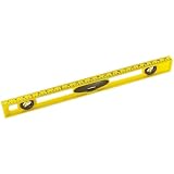
I have a cheap Stanley 24-inch level like this one:


The other day I noticed it didn't seem to be very accurate.  I checked by flipping it end for end on my workpiece, and sure enough the bubble settled in a different spot.

To measure how far off it is, I propped up the two ends with stacks of about 15 sheets of printer paper on my kitchen counter.  (It was important to support both ends because my counter isn't perfectly flat).  I added paper to one side until the bubble was dead center, then flipped the level end for end and had 9 sheets of paper (0.036") to one side before it was dead center again.

atan(0.036 / 24) = 0.086 degrees.  Since the vial is crooked and I'm flipping end for end, 0.086 degrees represents the angle between it being crooked to one side and being crooked to the other side, which is double the crookedness.  So the vial in my level is crooked by 0.043 degrees, +- 1/64" over 2 feet, or +-0.00075 inches per inch.

That doesn't sound like much, but it means that if I set two 8 foot beams indicated as "level", but flip the level around in between, they'll vary by 1/32 every 2 feet, for a total of 1/8" over the whole length.

Stanley doesn't make any accuracy claims for my level, but their fancier "professional I-beam level" claims accuracy of only 0.0015 inches per inch, twice as bad as mine!  But then their 24-inch aluminum box-beam level claims 0.0005 inches per inch, somewhat better than my 0.00075.

A fancier brand, Stabila, claims 1/32" over 72", which is also 0.0005 inches per inch.  The manual for their fancy digital level (which doesn't exactly inspire confidence with its poor formatting) claims 0.05 degrees within 0.1 degrees of level, and 0.2 degrees elsewhere.  So that's worse than my crappy level's 0.043 degrees even in the best case.  But then just below it they have a heading of "measuring accuracy of level" and claim 0.029 degrees, which is pretty confusing but just works out to the familiar 0.005 inches per inch.  Bottom line: the level could be off by 3x the allowed 0.0005 inches per inch, and the digital readout could still read it as dead level.

So the bottom line seems to be that for best results, I want a spirit level that'll allow me to adjust it, and even fancy digital levels aren't guaranteed to be any better than perhaps 3/16" over 8 feet.

(Just for my future reference, I also measured how much angle change there is between level and when the bubble just touches the first line.  That came out to 0.120" (about 1/8"), so a rise of about 1/16" per foot.)

Saturday, November 05, 2016

Supernight 5050 RGB LED string teardown


I've been having fun with this RGB LED string from Amazon with 300 5050 LEDs in a 16.4ft string.

One bug: after using it for a few minutes, it seems to have swapped the red and green columns of colored buttons: red displays green and green displays red.  The controller is nonvolatile: it remembers settings across powerdowns.

I set the controller to white (W button) full brightness and powered it with a bench supply.  I went as high as 13.8V since that's typical for a running car, and they know people will put them in their cars.  I briefly ran it upwards of 15V and it didn't immediately die, drawing about 3A.

The color temperature changes with applied voltage, going from yellow at lower voltages to very blue at high voltages.

The red LED first barely comes on at 5V 10mA.  The blue LED is last to come on, at around 9V 0.85A (so looks like you could power the string from a 9V battery) .  At 10V it draws 1.19A.  At 11.0V, it draws 1.56A.  At 12V it draws 1.96A.  At 13V it draws 2.33A, and at 13.8V it draws 2.65A.

At 12V and max brightness with just one color lit, red draws 1.17A, green draws 0.95A and blue draws 0.87A.

The output of the controller has 4 pins: White, Green, Red, Blue.  White connects to the positive rail (12V) and the three color channels are pulled down toward ground with PWM.  Each PWM channel supports 8 brightness levels if you've pushed one of the colored buttons.

If you press one of the DIY buttons, though, you get 64 levels per color.

PWM period is 4.1ms (244Hz frequency).

Under the hood, the heavy lifting is done by a trio of 70T03GH MOSFETs.  The microcontroller has no markings.  The remaining IC is a 24C02 EEPROM.

Here's an amusing aside: observe the wire harness in the top right of the photo below, which feeds the LED strip.  The LED strip's wires are colored white (12v), R, G, B, as expected.  But in the cable coming from the board: 12v is black instead of white, the green channel is a red wire marked B (but ever since my controller glitched, it's actually red), the red channel is a red wire marked G (but is actually green), and the blue channel is a blue wire marked R (and is actually blue).  So I bet the glitch I observed is part of a broader bug in which the controller flips around its channels, and which the manufacturer kept trying to fix by changing the order of wires in the harness.


The IR signal from the remote is received by an integrated IR receiver that produces serial for the microcontroller.  Normally high (5V), it pulls low for about 9ms for a start bit, back to high for 4ms, then sends data bits.  The data bits look to me like an RTZ code: high 600us, then high or low for 600us (depending on the data bit), then high 600us, then low 600us.  Looks like about 24 data bits.


Friday, September 23, 2016

BeagleBone to Android via USB Serial

As I mentioned in my last post, BeagleBone uses the Linux g_multi kernel module so that when you plug it into a PC, it appears to be a USB hub with USB-serial, USB-ethernet and USB storage devices attached.

In the other post I talk about how to plug a BeagleBone into an Android phone via USB and communicate between them using Ethernet.  Unfortunately it requires shutting off Wifi and cellular data.

So instead, I investigated communicating via USB serial instead of USB ethernet.  It should work out of the box, but none of the dozens of Android apps I tried could find the USB Serial device the BeagleBone provided.

Thus I used the same trick as before, replacing g_multi with a single-purpose device.  As in the last post, you'll have to comment out a big block of shell script in /opt/scripts/boot/am335x_evm.sh.

Then, instead of adding "modprobe g_cdc ${g_network}" and "usb0=enable" to explicitly load the USB Ethernet CDC driver, add:

modprobe g_serial
ttyGS0="enable"

When you reboot, you won't be able to "ssh 192.168.7.2" from your PC anymore.  Instead, you'll only get /dev/ttyACM0, and you'll need to login using a terminal emulator like minicom or screen.

(As before, you may want to make these changes while booting from a microSD card so that you can just pop the card out if it doesn't work).

After verifying that I could get in from my workstation, I connected my phone to the BeagleBone with an OTG adapter (careful!  Not all of them work right), then used the "Android USB Serial Monitor Lite" to connect to the BeagleBone.  (Open the "three dots" menu and select "Open Device", then send a newline and you should get a login prompt).

Connecting BeagleBone to newer Android Nexus phones (like Nexus 5X and Nexus 6P) via USB Ethernet

Update: Huh, I just discovered that this exists: Settings > developer options > networking > select USB configuration > RNDIS (USB ethernet).  But it doesn't seem to work.  So I suspect the RNDIS option there doesn't actually do anything.

The BeagleBone comes with a neat feature: when you plug it into your computer's USB port, the BeagleBone pretends it is a USB hub connected to several things: a serial port, USB storage and an ethernet adapter.  Thus you can point your PC's browser to http://192.168.7.2 and pull up the BeagleBone's built-in webserver, login via /dev/ttyACM0, or look through the files on its boot partition.

This all happens thanks to the g_multi Linux kernel module, which is one of several modules that allow devices with USB OTG ports to pretend to have things like storage, serial ports, ethernet and even MIDI ports.  g_multi aggregates a bunch of those together and presents them all to the host under a virtual USB hub.

This works great when connecting the BeagleBone to my Linux workstation over USB, and it also partly works when I connect the BeagleBone to my (stock) Nexus 5X: I can attach the BeagleBone to the phone using this VicTsing OTG adapter, and the BeagleBone will power itself from the phone and let me browse its USB storage.

I haven't had any success with the serial port, unfortunately.  I tried a bunch of different Android serial apps, and the phone seems to realize that the BeagleBone is offering a serial port, but I can't get any data between the devices.

Ethernet: if you want to talk from your Android phone to your beaglebone via TCP/IP over the USB cable, the first thing you'll have to do is, sadly, turn on airplane mode so that cellular and wifi data are disabled.  If one of those interfaces is active, pings and HTTP requests no longer make it to the BeagleBone.

Here's the other issue: recent phones like the Nexus 6P have a smaller set of USB Ethernet drivers enabled in the stock distro.  So with the BeagleBone in its default configuration, the Nexus 5X sees the ethernet interface just fine, but the Nexus 6P doesn't.

Fortunately, the g_multi can pretend to be one of two different *types* of USB Ethernet device.  The default is RNDIS, which apparently is a common thing on Windows, and is one of the drivers that got removed on the Nexus 6P.  The other is CDC, which is apparently a cleaner standard that manufacturers of USB Ethernet adapters can follow (so that each manufacturer doesn't have to invent their own driver interface).

Annoyingly, I can't find docs on g_multi's module parameters anywhere.  But I did manage to switch my BeagleBone from RNDIS to CDC ethernet with this change to /opt/scripts/boot/am335x_evm.sh.

As you can see, I just commented out the block of code that decides how to load g_multi, and instead I load the standalone g_cdc CDC Ethernet driver.  (This means you'll no longer get the USB storage and serial interfaces):


 # Added these two lines:  
 modprobe g_cdc ${g_network}  
 usb0=enable  
   
 # And commented out this big block:  
 ##g_multi: Do we have image file?  
 #if [ -f ${usb_image_file} ] ; then  
 #    modprobe g_multi file=${usb_image_file} cdrom=0 ro=0 stall=0 removable=1 nofua=1 ${g_network} || true  
 #    usb0="enable"  
 #    ttyGS0="enable"  
 #else  
 #    #g_multi: Do we have a non-rootfs "fat" partition?  
 #    unset root_drive  
 #    root_drive="$(cat /proc/cmdline | sed 's/ /\n/g' | grep root=UUID= | awk -F 'root=' '{print $2}' || true)"  
 #    if [ ! "x${root_drive}" = "x" ] ; then  
 #        root_drive="$(/sbin/findfs ${root_drive} || true)"  
 #    else  
 #        root_drive="$(cat /proc/cmdline | sed 's/ /\n/g' | grep root= | awk -F 'root=' '{print $2}' || true)"  
 #    fi  
 #  
 #    if [ "x${root_drive}" = "x/dev/mmcblk0p1" ] || [ "x${root_drive}" = "x/dev/mmcblk1p1" ] ; then  
 #        #g_ether: Do we have udhcpd/dnsmasq?  
 #        if [ -f /usr/sbin/udhcpd ] || [ -f /usr/sbin/dnsmasq ] ; then  
 #            modprobe g_ether ${g_network} || true  
 #            usb0="enable"  
 #        else  
 #            #g_serial: As a last resort...  
 #            modprobe g_serial || true  
 #            ttyGS0="enable"  
 #        fi  
 #    else  
 #        boot_drive="${root_drive%?}1"  
 #        modprobe g_multi file=${boot_drive} cdrom=0 ro=0 stall=0 removable=1 nofua=1 ${g_network} || true  
 #        usb0="enable"  
 #        ttyGS0="enable"  
 #    fi  
 #  
 #fi  


Be careful not to comment too much: you still want the "if [ "x${usb0}" = "xenable" ] " block below to be active so that the network interface gets set up correctly.

You might want to do all this while booted from a microSD card so that if you screw it up and can't access the BeagleBone over USB anymore, you can just pop out the card and fix am335x_evm.sh from your PC.

Tuesday, July 26, 2016

SeeedStudio Xadow with Ubuntu

Seems like every time I try to use the Xadow board, I have to spend hours getting it to program via the Arduino IDE.  This time, the solution seems to have been putting this in a file called /etc/udev/rules.d/78-xadow.rules and then rebooting:

ATTR{idVendor}=="2886",  ENV{ID_MM_DEVICE_IGNORE}="1"

Thursday, June 09, 2016

Which GPIO pins work with Adafruit_BBIO

Working with the Beaglebone can be really frustrating.  There are a lot of buggy libraries and incomplete docs, and the Sitara chip is really complicated, overloading its pins to do lots of different things.

Today I needed 8 GPIO pins for a test harness.  I looked at the diagrams for the P8 and P9 headers and picked some likely-looking pins.  I used the Adafruit_BBIO python library and set them up as outputs, then toggled them and watched with the meter.  Three of them didn't work.

So I changed my script to try to toggle *all* the pins on P9, even the ground and VCC pins.  Of course this doesn't bother Adafruit_BBIO because it has no error checking (ugh).  Here are the pins that worked as GPIO outputs.

Note that this is from my Beaglebone *Green*.  On the Beaglebone *Black* you'd probably need to disable HDMI for some of these pins to work.

Beware: I repeated this test several times across reboot and power down, and some of the pins worked the second or third time that didn't work the first.  It's possible that's sloppiness on my part, but my intuition says no, and that Adafruit_BBIO isn't initializing the pins correctly, so there's some random chance at play.  The best reference I've found so far in how stuff actually works is "Exploring Beaglebone", which is unfortunately a non-free book, but very well written.

P8_7
P8_8
P8_9
P8_10
P8_11
P8_12
P8_13
P8_14
P8_15
P8_16
P8_17
P8_18
P8_19
P8_26
P8_27
P8_28
P8_29
P8_30
P8_31
P8_32
P8_33
P8_34
P8_35
P8_36
P8_37
P8_38
P8_39
P8_40
P8_41
P8_42
P8_43
P8_44
P8_45

P9_11
P9_12
P9_13
P9_14
P9_15
P9_16
P9_23
P9_24
P9_25
P9_26
P9_27
P9_28
P9_29
P9_30
P9_31
P9_41
P9_42


Adafruit_BBIO bugs

First bug was mine.  I was doing "import Adafruit_BBIO as GPIO" instead of "import Adafruit_BBIO.GPIO as GPIO".  That gave this error once I started trying to use it:

$ ./test.py
Traceback (most recent call last):
  File "./test.py", line 5, in <module>
    GPIO.setup("P9_11", GPIO.OUT)
AttributeError: 'module' object has no attribute 'setup'

The other bug was theirs: the code appeared to be working, but the GPIO pins weren't changing state.  Turns out there's no error checking in the library (ugh).  So it wasn't giving any errors when I failed to run the script as root.

Wednesday, February 24, 2016

Beaglebone black PWM minimum frequency

By trial and error, I just figured out that 1 billion is the longest period you can set for (at least this particular) PWM channel.

root@beaglebone:/sys/devices/ocp.3/pwm_test_P9_31.13# echo 1000000000 > period
root@beaglebone:/sys/devices/ocp.3/pwm_test_P9_31.13# echo 1000000001 > period 
bash: echo: write error: Numerical result out of range

The value is in nanoseconds, so that gives a minimum frequency of 1Hz for PWM on beaglebone black.

Also note that it won't let you set the period lower than the duty cycle setting (which we should really call the pulse width instead):

root@beaglebone:/sys/devices/ocp.3/pwm_test_P9_31.13# echo 2000 > duty
root@beaglebone:/sys/devices/ocp.3/pwm_test_P9_31.13# echo 1000 > period 
bash: echo: write error: Invalid argument
root@beaglebone:/sys/devices/ocp.3/pwm_test_P9_31.13# echo 500 > duty
root@beaglebone:/sys/devices/ocp.3/pwm_test_P9_31.13# echo 1000 > period 

Friday, February 19, 2016

Connect beaglebone black to android via USB OTG

With the right USB OTG cables, I was able to connect my Nexus 5X to a beaglebone black and a beaglebone green.  I had to try several cables before the beaglebone would power up; I suspect it's the USB-C adapter that's the most problematic.  This is the USB-C OTG cable that worked.

Once the board booted, I got a notification on my phone about the beaglebone USB storage device becoming available.  But I wanted to send data back and forth between an android app and a beaglebone process, so the network interface was the important thing to me.

When I connect the beaglebone to my PC, it shows up as a USB ethernet adapter, and I can talk to it at 192.168.7.2.  I downloaded an android app called "Terminal Emulator", and when I ran "ifconfig" I could see that I had an eth0 device with IP 192.168.7.1.  But I couldn't connect to it.

But if I turn on airplane mode, oddly, I can connect just fine by putting "192.168.7.2" in the address bar of the browser.  I haven't figured out yet whether it's possible to have LTE or Wifi on and still reach the beaglebone; perhaps it's just something to do with the IP addresses used by the Wifi or beaglebone.

Tuesday, January 26, 2016

BeagleBone DMA notes

I've been transferring data between the BeagleBone's PRUs and main memory.  If I use the PRU's SBBO instruction to store a range of PRU registers to main (DDR) memory, I find that I get around 600MB/s -- not bad!

But surprisingly, when I try to read that data back, the main CPU seems to go much slower.

I wrote some sample code for the main CPU to sum up all the bytes in a big (many MB) ordinary buffer.  I got ~300MB/sec.  Using the LDM instruction I got that up to 600MB/sec and in one case over 1GB/sec.  So in general the main CPU seems to have no trouble accessing main memory.

But when I run the same code on the buffer allocated by the uio_pruss kernel module, I get only about a tenth of that: 30MB/s, or closer to to 40MB/s when using LDM.

Kumar Abhishek from the BeagleLogic project helped me understand what was going on.  The uio_pruss module allocates that buffer using dma_alloc_coherent(), which is the standard way that linux kernel modules talk to DMA-based peripherals when they need to exchange smallish amounts of data quickly.  It tells the kernel that somebody else is going to be writing to main memory via DMA, so for this block of data, make sure we bypass the cache for every single memory access.

For larger blocks of data travelling in one direction, CPU -> peripheral or peripheral <- CPU, the Dynamic DMA mapping Guide describes that the standard approach is to kmalloc() the memory in the kernel module, then use functions like dma_map_single(), dma_unmap_single(), dma_sync_single_for_cpu(), dma_sync_single_for_device() to make sure entire buffers are safe for access by the peripheral or CPU.

That way, rather than every memory access having to bypass the cache, the kernel can make sure it's safe for the CPU to access everything in the block now that the peripheral is done with it, or vice versa.

Unfortunately, though, on the ARM A8 CPU in the beaglebone, making sure a buffer doesn't already have stale data in the cache (which can happen unexpectedly due to things like speculative preloading) requires the kernel to walk cache line by cache line through the entire buffer, taking longer than the memory transfer it's preparing for!

Kumar reports that he gets upward of 200MB/sec using this approach, dominated by the dma_* kernel calls.  I tried it myself with a simple kernel module and got a bit over 100MB/sec, so it seems plausible to me.

This thread, "dma_sync_single_for_cpu takes a really long time", is worth reading all the way through.

The only other way I can think of to get faster CPU access to big chunks of data from the PRUs is to tell the L1 and L2 caches to flush themselves, then access the data without calling the dma_sync_* functions at all.  The danger there is that it's very much tied to the specific CPU architecture and is very much not the recommended approach, so nobody's going to sympathize if you get corrupt data, and the only way to know if you've done it right is to try to test all the edge cases you can think of.

Monday, December 21, 2015

BeagleBone Access Point (and working around udhcpd)

Warning: it's easy to screw this stuff up and lose the ability to ssh into the beaglebone when you reboot.  Usually it was as simple as manually setting the IP address on my laptop, but you may not be so lucky.  You may not want to attempt this if you don't have a good handle on TCP/IP networking.

My Keebox W150NU seems to be doing a good job with a BeagleBone black as a wifi access point.  (I get about 3MB/s beaglebone -> laptop).  Beware that lots of other adapters (eg., Edimax and D-Link) work really poorly or not at all with the BeagleBone.

With a newer BeagleBone green, the W150NU was recognized out of the box, but on an older BBB with another adapter I had to update the kernel first:
Update kernel if your wifi adapter isn't detected (or if you just want to be up to date):
First I did 'sudo apt-get update ; sudo apt-get dist-upgrade'
Then I upgraded the kernel so it'd recognize the usb wifi adapter:
'cd /opt/scripts/tools ; git pull ; ./update_kernel.sh' 
On BeagleBone Green they tweaked a file to say "BBG" instead of "BBB", so I had to revert it with: 'cd /opt/scripts ; git checkout tools/eMMC/init-eMMC-flasher-v3.sh' then 'git pull' again before I could run the 'update_kernel.sh' script.
Rebooting, the W150NU appeared as wifi2.

Next, I followed the instructions here to set up hostapd.  

First, 'sudo apt-get install dnsmasq hostapd'

Here's my /etc/hostapd/hostapd.conf (beware leading and trailing spaces, or hostapd.conf will refuse to start):

### Wireless network name ###
interface=wlan0
#
### Set your bridge name ###
#bridge=br0

#driver
driver=nl80211

country_code=US

ssid=beaglebone

channel=7

hw_mode=g

# # Static WPA2 key configuration
# #1=wpa1, 2=wpa2, 3=both
wpa=2

wpa_passphrase=yourpassword

## Key management algorithms ##
wpa_key_mgmt=WPA-PSK
#
## Set cipher suites (encryption algorithms) ##
## TKIP = Temporal Key Integrity Protocol
## CCMP = AES in Counter mode with CBC-MAC
wpa_pairwise=TKIP
#rsn_pairwise=CCMP
#
## Shared Key Authentication ##
auth_algs=1
## Accept all MAC address ###
macaddr_acl=0
#enables/disables broadcasting the ssid
ignore_broadcast_ssid=0
# Needed for Windows clients
eapol_key_index_workaround=0

And don't forget to set this in /etc/defaults/hostapd:

DAEMON_CONF="/etc/hostapd/hostapd.conf"
I couldn't get dnsmasq or isc-dhcp-server to work consistently, though.  Turns out that 'netstat -nlp' showed udhcpd was binding to 0.0.0.0 on port 67 (which is a bug, since it ignores the "interface" option), so the other dhcp servers can't start.

Hint: /var/log/daemon.log is where a lot of the error messages show up.

I fixed that with 'mv /usr/sbin/udhcpd /usr/sbin/udhcpd.disabled', although it would probably have been better to 'apt-get purge udhcpd'.

Here's my /etc/dnsmasq.conf:

interface=usb0
dhcp-range=192.168.7.1,192.168.7.1,4h

interface=wlan0

dhcp-range=192.168.4.2,192.168.4.10,4h

And I also added this to /etc/network/interfaces:
auto wlan0
iface wlan0 inet static
    address 192.168.4.1
    netmask 255.255.255.0
    network 192.168.4.0
    gateway 192.168.4.1

That seems to do it, except that I have to "ifup wlan0" after startup on my BeagleBone Green.  The Black doesn't seem to need that for some reason I haven't figured out yet.

Getting BeagleBone to recognize wifi adapters by upgrading the kernel

My beaglebone black wasn't recognizing my wifi adapter.  apt-get update ; apt-get dist-upgrade didn't help, and I noticed that it wasn't upgrading the kernel.

Looks like the way to get kernel updates is to use /opt/scripts/tools/update_kernel.sh.  When I first tried it, I got errors like "The certificate of `rcn-ee.net' is not trusted".

So the first step was to "git pull" down the latest version of the update_kernel.sh script, then run it.  Upon reboot, it recognized the wifi adapter.

Also note that beaglebone doesn't always do USB hotplug right, so I made sure to reboot after plugging in the adapter.

Also, even after updating the kernel, my Edimax and D-Link adapters show up but won't associate to an access point.  The Keebox W150NU seems to be working well, though.

Update: Even with the W150NU, I had trouble connecting to public networks.  I noticed this in dmesg: "deauthenticating from by local choice (reason=3)", which led me to a page recommending that I kill wpa_supplicant, and that fixed it.

Wednesday, December 16, 2015

BeagleBone Black/Green bus speeds

USB Host (big type A jack): 20MB/s writing to a Seagate USB3 2TB portable (spinning) hard disk (required plugging a 5V 4A power supply into the BeagleBone Black's power jack).  On BeagleBone Green, I got corruption with the Seagate disk, even when I powered the board from a bench supply.  With this Samsung 64GB USB flash drive I get 14-18MB/s write on both BeagleBone Green and Black.

Disk: 4.3MB/s writing to onboard flash, and 7.1MB/s to a SanDisk Ultra 64GB microSD card.  On BeagleBone Green, I get 9.4MB/s to onboard flash, and 6.8MB/s to the same SanDisk microSD card.

Network: Using netcat with the USB ethernet interface, I get 7.6MB/s upstream (to my laptop).  With the 100baseT jack I get 11.2MB/s upstream.  If I use ssh with its default cipher, I get about 10MB/s, but that goes back up to 11.1MB/s if I use "-c arcfour".

Compression: gzip -1 gives me 4.1MB/s on text generated by "cat /dev/urandom data | od -x".  I tried lz4 as well and it was almost exactly the same speed.